Identify hazards
PCBU’s, including principal contractors and masonry contractors, are responsible for identifying hazards associated with masonry wall construction, such as unplanned collapse.
Factors to consider include :
- walls previously identified on the design drawings as needing temporary supports
- any features of the wall that may affect its strength – e.g. control joints, lintels, damp proof course, bond type or openings
- worker walkways or access paths
- plant, equipment and material movement, including delivery and storage areas
- the proposed sequence for the wall construction, (including whether you will build cross walls or returns at the same time as the wall so that they provide some support to each other, the rate of construction and proposed stop heights)
- the structural adequacy of the foundations
- existing or proposed excavations
- walls adjacent to another property or a public area
- likely weather conditions for the location and season – e.g. wind (see table 1), extreme temperatures and rain
- the proposed height, width and layout of walls (see table 2 and figure 1).
Table 1: Wind characteristics and recommended actions on unsupported masonry walls.
| Description | Wind gust speed | Wind characteristics | Recommended actions |
|---|---|---|---|
| Low winds | 0-19 km/h (0-11 knots) | Small branches and dust not moving | Safe to build masonry wall up to heights in table 2. Brace walls, then masonry work may continue if wind is not likely to increase |
| Moderate winds | 20-29 km/h (12-16 knots) | Raises dust and loose paper; small branches are moving | |
| Fresh winds | 30-39 km/h (17-21 knots) | Small trees begin to sway; crested wavelets form on inland waters | Stop all masonry work at heights above the fresh wind heights in table 2 and brace walls |
| Strong winds and higher | over 39 km/h (over 21 knots) | Large branches in motion; whistling heard in overhead power lines; umbrellas used with difficulty | Stop all masonry work and establish a no-go zone around masonry walls |
Source: Based on the Beaufort Wind Scale.
Note: Assess the wind speed at the wall location
Table 2: Maximum unsupported wall height – single skin (leaf) or cavity wall
| Type | Width in mm | Maximum unsupported wall height (mm) Low to moderate winds | Maximum unsupported wall height (mm) Fresh winds |
|---|---|---|---|
| Brick | 90 | Single skin 1500 Cavity 2100 | Single skin 750 Cavity 1050 |
| 110 | Single skin 1800 Cavity 2500 | Single skin 900 Cavity 1250 | |
| Block | 90 | 1050 | 525 |
| 140 | 1600 | 800 | |
| 190 | 2500 | 1250 |
Note: This table is based on a maximum spacing of 3 m between supports, and applies to standard-weight extruded or pressed-clay bricks and hollow-core concrete blocks. Lower heights apply for lighter weight bricks or blocks – seek engineering or manufacturer’s advice.
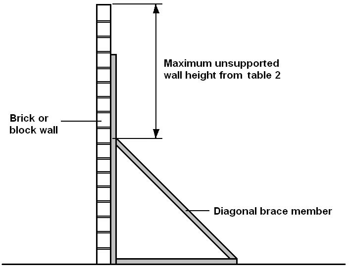
Figure 1 - Illustration of unsupported wall height above a brace
Note 1: The upright member above the diagonal is ignored, as it may not be rigid enough to provide support. If the brace was not in place, the maximum unsupported wall height from table 2 would apply from ground level.
Note 2: Unless the brace is structurally connected to wall near the top of the diagonal, usually a through connection with plate on the far side, it is only preventing the wall falling toward the brace and another brace may be required on the other side of the wall.